
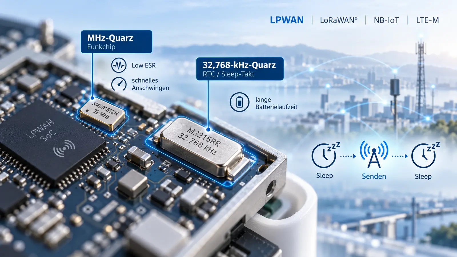
1. Two clock sources, two tasks
A typical LPWAN device for LoRaWAN®, NB-IoT, LTE-M or similar wireless technologies operates with two crystal oscillators. The MHz crystal oscillator provides the reference for the radio chip and thus determines the carrier frequency, channel spacing and timing of the radio link. It operates only during the brief measurement, transmission and reception phases. The 32.768-kHz crystal oscillator drives the real-time clock (RTC) and runs continuously, even in sleep mode, during which LPWAN devices spend the vast majority of their service life.
This gives rise to two different optimisation objectives: for the MHz crystal, a fast and reliable start-up is essential every time the device wakes up. With the 32.768 kHz crystal, the priority is to minimise the continuous current of the RTC oscillator whilst maintaining a high settling margin. Both objectives can be achieved using the same parameter: a low equivalent series resistance (ESR).
2. The correct frequency and design
The frequency of the MHz crystal is determined by the radio IC used. In LPWAN applications, 24 MHz, 32 MHz, 38.4 MHz, 39 MHz, 40 MHz, 48 MHz, 50 MHz and 52 MHz are commonly used. The chip manufacturer’s datasheet and reference design are always decisive, including the load capacitance and frequency accuracy specified therein.
The package type depends on the available module area. PETERMANN-TECHNIK offers the following series for LPWAN applications:
| Series | Frequency range | Ceramic housing | Pads |
|---|---|---|---|
| SMD03025/4 | MHz | 3.2 x 2.5 mm | 4 |
| SMD02016/4 | MHz | 2.0 x 1.6 mm | 4 |
| SMD01612/4 | MHz | 1.6 x 1.2 mm | 4 |
| SMD01210/4 | MHz | 1.2 x 1.0 mm | 4 |
| M3215RR | 32,768 kHz, ESR max. 50 kΩ | 3.2 x 1.5 mm | 2 |
| M2012 | 32,768 kHz | 2.0 x 1.2 mm | 2 |
| M1610 | 32,768 kHz | 1.6 x 1.0 mm | 2 |
3. ESR, negative resistance and transient response
From an electrical point of view, a quartz crystal operating near its resonance can be described by the Butterworth–Van Dyke equivalent circuit: a series circuit comprising dynamic inductance Lm, dynamic capacitance Cm and the loss resistance Rm (ESR), with the static capacitance C0 in parallel. The ESR summarises all losses in the resonator. The oscillator stage of the IC must compensate for these losses.
In the Pierce circuit commonly used in radio chips and microcontrollers, the inverter, together with the load capacitors C1 and C2, produces a negative input impedance. In simplified terms, disregarding the influence of C0, the following applies:
−Rneg ≈ − gm / (ω² · C1 · C2) where ω = 2π · f
gm: slope of the oscillator stage; C1, C2: external load capacitors, including pin and trace capacitances
To ensure the oscillator stabilises reliably, the magnitude of the negative resistance must be significantly greater than the ESR, regardless of temperature, supply voltage, ageing and component variation. This ratio is described by the safety factor:
SF = |−Rneg| / ESRmax
In practice, values of SF ≥ 5 are considered safe. The IC manufacturer’s specifications take precedence.
The formula illustrates the leverage effect of the crystal: if the ESR is halved, the safety factor doubles provided the circuit remains unchanged. Alternatively, the same safety factor can be achieved with a lower slope gm and thus with a lower oscillator current. This is precisely where our exclusive LRT design (Low ESR Resonator Technology) comes into play, which is engineered for particularly low resonant resistances.
4. Why the ESR determines the rise time
After switch-on, the oscillation amplitude increases exponentially from the noise level. The time constant of this rise depends directly on the difference between the negative resistance and the ESR:
τ ≈ 2 · Lm / ( |−Rneg| − ESR )
tstart ≈ τ · ln( Aend / A0 )
A0: Start amplitude (noise), Aend: steady-state amplitude
The greater the difference between |−Rneg| and ESR, the shorter the settling time. A low ESR has a particularly noticeable effect when the oscillator stage is operating at the limit, for example at low battery voltage, low temperatures or with oscillators configured for low power consumption. A calculation example: If |−Rneg| is twice the ESR and the ESR is halved, the time constant τ is reduced by a third.
For a 32.768 kHz crystal, Lm is, due to its tuning-fork design, several orders of magnitude greater than for an MHz crystal. The settling time is therefore typically in the range of hundreds of milliseconds up to seconds. A small settling time reserve is particularly critical here; in the worst-case scenario, the RTC may fail to start at all after a battery change or in cold conditions.
5. How the quartz crystal affects the system current
MHz quartz: Energy per wake-up cycle
Whilst the MHz oscillator is starting up, the radio chip waits, and, depending on the architecture, the microcontroller is also active. The energy consumed in this process is repeated with every wake-up cycle:
ΔEday ≈ N · UB · ISys · Δtstart
N: wake-up events per day, UB: battery voltage, ISys: system current during ramp-up, Δtstart: reduction in ramp-up time
Calculation example: A sensor wakes up once per minute, i.e. N = 1,440 times per day. If the settling time is reduced by 0.5 ms, this saves 0.72 s of system waiting time per day, amounting to around 44 minutes of active operation over a ten-year service life.
32.768 kHz crystal: RTC continuous current
The RTC oscillator runs round the clock. Many ICs allow the slope or bias current of the 32.768-kHz oscillator to be adjusted, or automatically regulate the amplitude. A crystal with low ESR achieves the required safety factor even with a lower slope. As the RTC oscillator can account for a significant proportion of an LPWAN device’s quiescent current, any reduction here has an impact over the entire service life.
Drive Level
The power dissipated in the crystal (drive level) is calculated from the crystal current and the ESR. It must not exceed the limit specified in the data sheet, which is particularly important to note in the case of miniature crystals:
DL = IQ² · ESR ≈ ESR · ( 2π · f · (C0 + CL) · UQ )²
IQ: RMS value of the quartz current, UQ: RMS value of the voltage across the quartz
6. The 32.768 kHz crystal: why we recommend the M3215RR
With tuning-fork crystals, the ESR generally increases significantly as the size decreases. The smaller the 32.768 kHz crystal, the more limited the settling time becomes for the same oscillator stage, and the greater the slope and current required by the RTC oscillator.
The M3215RR combines a very low ESR of max. 50 kΩ with the most competitive price amongst miniaturised 32.768 kHz crystal oscillators. Our recommendation for design-in is therefore: you save space most effectively with MHz crystals; for 32.768 kHz crystals, opt for low ESR.
7. The tried-and-tested combination
This recommendation was very well received in the designs we have worked on. A MHz crystal oscillator from the SMD01612/4 or SMD02016/4 in combination with the M3215RR. This combination offers a compact design and low cost and, in our experience, delivers the greatest savings in system power consumption. As our MHz and kHz crystal oscillators are based on the exclusive LRT design, both clock sources start up very quickly and reliably due to their very low resistance in the circuit.
| Clock | Recommended series | Reason |
|---|---|---|
| MHz (radio chip) | SMD01612/4 or SMD02016/4 | compact design, LRT design, fast settling time on each wake-up |
| 32,768 kHz (RTC) | M3215RR | ESR max. 50 kΩ, most affordable miniaturised 32.768 kHz crystal, low RTC continuous current |
8. Load capacity and frequency accuracy
The quartz will only oscillate at its nominal frequency if the circuit provides the specified load capacitance CL. This is made up of the external capacitors and the stray capacitances of the pins and traces:
CL = ( C1 · C2 ) / ( C1 + C2 ) + Cstray
for C1 = C2: C1 = C2 = 2 · ( CL − Cstray )
Cstray: typically a few pF, depending on the IC and layout
If the actual load capacitance deviates from the nominal value, the frequency shifts. The sensitivity (pulling sensitivity) is:
S ≈ − Cm / ( 2 · ( C0 + CL )² ) · 106 [ppm/pF]
Small crystals have a lower dynamic capacitance Cm and are therefore slightly less sensitive to capacitance deviations. For the radio link, the total frequency budget comprises the adjustment tolerance at 25 °C, temperature stability, ageing and load capacitance error. This budget must fall within the specifications of the radio IC. If a chip requires tighter frequency accuracy over temperature than a crystal oscillator can provide, the manufacturer specifies a TCXO. In this case, we can also advise you on suitable crystal oscillators.
Provided the IC permits it, a lower load capacitance reduces the oscillator current: smaller C1 and C2 increase the negative resistance according to the formula in Section 3. At the same time, however, the pulling sensitivity S increases, meaning that stray capacitances have a greater impact on the frequency.
9. Layout guidelines
- Position the quartz as close as possible to the IC’s oscillator pins; keep the trace lengths short and symmetrical.
- Provide a continuous ground plane beneath the quartz; do not route any signal lines beneath the housing.
- Maintain a safe distance from switching regulators, clock lines and RF paths.
- With a 32.768 kHz crystal, be mindful of leakage currents: flux residues and moisture can place a load on the very high-impedance oscillator node.
- Determine the stray capacitance Cstray on the finished board and then definitively set C1/C2.
10. Design-in checklist
- Take the frequency, load capacity and frequency accuracy from the data sheet and reference design of the radio IC.
- Select the MHz variant based on the module footprint; preferably SMD01612/4 or SMD02016/4.
- For the RTC, provide the M3215RR.
- C1/C2 taking into account Cstray when dimensioning.
- Check that the safety factor SF = |−Rneg| / ESRmax ≥ 5 across the temperature and supply voltage range.
- Measure the settling time and drive level on the finished board.
- Measure the frequency on the board and verify the load capacity.
Frequently Asked Questions: Quartz crystals for LPWAN applications
About PETERMANN-TECHNIK
PETERMANN-TECHNIK GmbH, based in Landsberg am Lech, has specialised in quartz crystals and quartz oscillators since 1996. Together with our manufacturing partner, with whom we have had an exclusive partnership for Europe since 1996, we offer quartz crystals with particularly low resonance resistances using LRT technology (Low ESR Resonator Technology).
As an ISO 9001-certified company, we take full responsibility for the quality of our products. Our application engineers support developers from the initial circuit diagram right through to testing on the finished board.
Are you developing an LPWAN module? Our application engineers can assist you with crystal selection, load capacity and start-up reliability. Contact: www.petermann-technik.de
SUGGESTED LINKS
- Selecting the right crystal for LoRaWAN® applications
- LRT crystal oscillators
- Checking the negative input resistance −Rneg and the settling time margin
- Check the ESR (Equivalent Series Resistance) of the crystal
- Measure the start-up time of the quartz oscillator
- Measure the drive level and quartz current
- Determining the values of external capacitors C1/C2 and calculating Cstray
- Determining parasitic capacitances Cpar on the printed circuit board
- Measuring and verifying load capacitance CL in the circuit
- Why won’t my 32.768 kHz crystal oscillate?
- Quartz configurator


